
What causes vibration in multirotor UAV propulsion systems
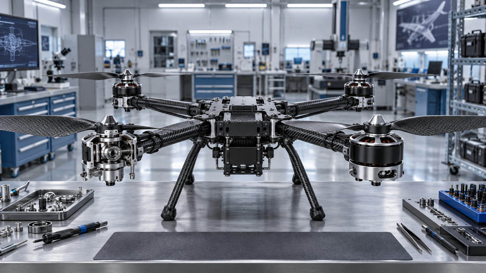
Why propulsion vibration deserves immediate attention
Vibration in a multirotor aircraft is rarely just a comfort or noise issue. It can degrade attitude estimation, create unstable flight behavior, loosen fasteners, shorten bearing life, damage wiring, and obscure the original fault behind secondary damage. For an after-sales technician, the practical question is not simply whether vibration exists. It is whether the vibration is generated by a rotating component, amplified by the structure, or introduced by an electrical or control problem that changes motor torque unevenly.
A useful first distinction is between a vibration that appears at a particular motor speed and one that remains across a wide throttle range. A narrow speed band often points toward resonance, propeller tracking, or an imbalance that becomes prominent at a certain rotational frequency. Vibration that rises steadily with throttle is more likely to come from the propeller, motor, adapter, shaft, or another rotating part. Random shaking, pulsing, or vibration accompanied by motor-speed changes may require inspection of the ESC, wiring, flight-control tuning, or power supply.
The fastest repairs usually come from isolating the source before replacing parts. Changing multiple propellers, motors, and controllers at once may make the symptom disappear temporarily, but it removes the evidence needed to identify a recurrent assembly, handling, or maintenance problem.
Propeller faults are the most common starting point
Propellers are exposed components. They can be damaged by minor ground contact, transport pressure, debris impact, poor storage, repeated heating, or improper installation. A propeller may look intact from a normal viewing distance while still carrying enough imbalance to affect a sensitive multirotor platform.
Static imbalance occurs when one blade or one side of the hub is heavier than the other. Dynamic imbalance is more difficult: the propeller may balance on a simple balancer yet still produce vibration in operation because blade tracking, stiffness, pitch distribution, or hub geometry differs between blades. A chipped blade, a repaired composite edge, or a blade with moisture or contamination can also produce a problem that is not obvious during a brief visual inspection.
Inspect propellers before evaluating electronics. Remove them and check for the following:
- Cracks around the root, hub bore, folding joint, or blade leading edge.
- White stress marks, delamination, soft spots, or local deformation in composite parts.
- Uneven blade profile, edge damage, or accumulated contamination.
- Hub wear that allows the propeller to sit off-center on the adapter.
- Incorrect propeller direction, incorrect installation sequence, or mismatched propeller pairs.
- Folding blades that do not open symmetrically or have unequal hinge friction.
A replacement propeller is often the correct action after a strike, but technicians should avoid assuming that any new propeller is automatically balanced and dimensionally consistent. Check the new part, its mounting interface, and its clearance from arms, landing gear, payload supports, and cable routes. A propeller that flexes into a nearby object at high thrust can create vibration only under load, making bench inspection misleading.
Blade tracking also matters. When the tips of two blades do not follow the same rotational plane, the propeller creates a cyclic force even if its static mass balance appears acceptable. Tracking errors can result from a bent hub, distorted folding mechanism, improper washer placement, a damaged adapter, or a propeller that has been tightened against an uneven mounting face.
Motor bearings, shafts, and mounting interfaces
If vibration remains after propeller substitution, inspect the motor assembly closely. Brushless motors can continue to run and produce acceptable thrust even after bearing wear has begun. The resulting vibration may be subtle at low speed and become pronounced as rotational speed rises.
With power removed and propellers detached, turn each motor by hand. The feel should be smooth and consistent across comparable motors. Roughness, clicking, side play, axial play, or a noticeable difference in rotational resistance warrants further inspection. A damaged bearing may also create intermittent vibration that changes after the motor warms up.
A bent shaft can produce a similar symptom. It may follow a propeller strike, a hard landing, or force applied to the motor during transport. On motors with removable bells or shafts, inspect for visible runout and signs of rubbing between the rotating bell and stationary stator. Scoring marks, metallic dust, or uneven clearance are useful indicators. Replacing only the bearing may not solve the issue if the shaft, bell, or bearing seat was distorted by the same event.
The motor mounting surface deserves equal attention. Loose screws allow a motor to move relative to the arm and amplify vibration. Screws that are too long can contact the stator windings or interfere with internal motor components. Incorrect thread engagement, stripped inserts, cracked arm ends, and missing washers can all alter the stiffness of the joint. A motor can remain firmly attached during a hand check but shift under torque and thrust loads.
For maintenance records, it helps to note whether the vibration follows a physical motor position or follows the motor when it is exchanged with another arm. If the fault moves with the motor, focus on the motor, propeller interface, and controller channel associated with that motor. If it stays at the same arm position, the arm, mounting plate, wiring restraint, or local frame structure becomes more suspect.
Frame resonance can turn a minor defect into a flight problem
Every airframe has natural frequencies. Arms, center plates, landing gear, payload mounts, battery trays, camera isolators, and covers can all vibrate at different frequencies. A small excitation from a normal propeller or motor can become much larger when motor speed coincides with one of these structural frequencies.
This explains why a platform may be smooth while hovering, then develop a strong buzz at a specific throttle setting, payload weight, battery state, or flight mode. The source may still be a slightly imbalanced propeller, but the visible shaking is being magnified by the airframe rather than generated entirely at the propeller.
After any impact, inspect arms and central plates for cracks, loose fasteners, crushed carbon laminate, damaged bonded joints, and distorted motor mounts. Carbon-fiber arms can have internal damage that is difficult to see. A change in stiffness may be enough to move the resonance into the normal operating speed range. Do not treat a repaired or replaced arm as equivalent to the original configuration unless its alignment and clamping condition are restored consistently.
Accessories often create overlooked resonance paths. A loose GPS mast, payload bracket, antenna mount, battery strap buckle, camera support, or cable bundle can vibrate independently and transmit motion to the flight controller or sensor package. This may be mistaken for propulsion vibration because the symptom appears only when motors are running. Secure accessories and wiring, then reassess the aircraft before changing propulsion components.
Soft mounting is not an automatic cure. Isolators can reduce high-frequency transmission to a flight controller or payload, but they can also introduce low-frequency movement when they are too soft, overloaded, aged, or installed with insufficient restraint. The goal is controlled isolation within the expected operating load, not maximum flexibility.
Electrical and control faults can produce mechanical-looking vibration
Mechanical checks should come first, but uneven motor torque can create vibration without a damaged propeller or bearing. ESC timing problems, poor solder joints, damaged phase wires, connector resistance, intermittent power distribution, or an unsuitable motor-controller combination can cause one motor to respond differently from the others.
Electrical faults often leave clues that differ from a purely mechanical imbalance. The affected motor may run hotter, start less smoothly, make an irregular sound, hesitate during throttle changes, or show a different current draw when compared under the same controlled conditions. Heat discoloration, hardened insulation, loose connectors, and damaged wire strands near arm joints are all relevant inspection points.
A Multirotor UAV Propulsion System should be checked as a matched set rather than as isolated parts. Motor KV, propeller size, ESC firmware settings, battery voltage, and flight-controller output configuration affect how torque is delivered. Replacing an ESC with a unit that has materially different timing behavior, startup characteristics, or control response can create a new problem even when the replacement appears electrically compatible.
Flight-controller filtering and control tuning can also reveal or amplify propulsion issues. Excessive filter settings may delay useful control response; insufficient filtering may allow motor and propeller vibration to contaminate gyro signals. Aggressive gains can drive rapid motor-speed corrections that look like vibration but are actually a control-loop response. However, tuning should not be used to conceal a mechanical fault. If a platform needs unusual filtering or substantially reduced gains after a propeller strike or maintenance event, return to physical inspection.
A practical isolation sequence
A disciplined sequence reduces unnecessary part replacement. Begin with the aircraft de-energized and propellers removed. Check the frame, arm attachments, motor screws, propeller adapters, wiring supports, and visible damage. Rotate every motor manually and compare feel, play, and resistance. Then inspect propellers individually rather than treating a set as interchangeable.
For a controlled powered check, use an appropriate restrained test setup and keep personnel clear of the propeller plane. Compare motor startup behavior and sound at low speed first. Increase speed gradually only when the platform is secured and the test condition permits it. A sudden increase in vibration at one speed band should be recorded because it is useful evidence of resonance or rotating-part runout.
When a suspect component is found, make one controlled change and retest. Replace or relocate only the item being evaluated, then verify whether the vibration level and its throttle-dependent pattern changed. This is slower than swapping several parts at once, but it produces a defensible maintenance result and helps identify whether the underlying issue was component damage, assembly variation, or structural resonance.
What to record before returning the aircraft to service
A vibration issue should not be closed simply because the aircraft can lift off. Record the symptom, flight condition, affected arm or motor position, propeller condition, corrective action, and result of the post-repair check. Where the aircraft supports telemetry or flight-log review, compare motor outputs, gyro traces, and temperature indications before and after repair. The value is not in finding a perfect trace; it is in confirming that an abnormal pattern has been reduced and that one motor is no longer compensating disproportionately.
Also inspect nearby components after resolving the primary fault. Prolonged vibration can loosen fasteners, fatigue solder joints, damage cable insulation, wear connectors, and affect payload mounts. Recheck torque retention and wire routing after the first flights, particularly following motor, arm, propeller adapter, or structural repairs.
Most multirotor vibration problems can be traced to a small group of causes: damaged or poorly seated propellers, worn motor components, loose or altered mounting structures, and inconsistent electrical drive. The repair becomes much more reliable when technicians identify the vibration pattern first, inspect the mechanical path before adjusting software, and verify the result under the operating conditions where the fault originally appeared.
First class quality service and professional after-sales team.
Get in Touch
*We respect your confidentiality and all information are protected.